Interfacing a rotary encoder with an ESP32 microcontroller is a straightforward process that can be achieved using a few essential components and a small amount of programming knowledge. This article will explore the steps involved in interfacing a rotary encoder with the ESP32 and discuss some of the benefits of using this input device.

How to Interface Rotary Encoder with ESP32?
What is a Rotary Encoder?
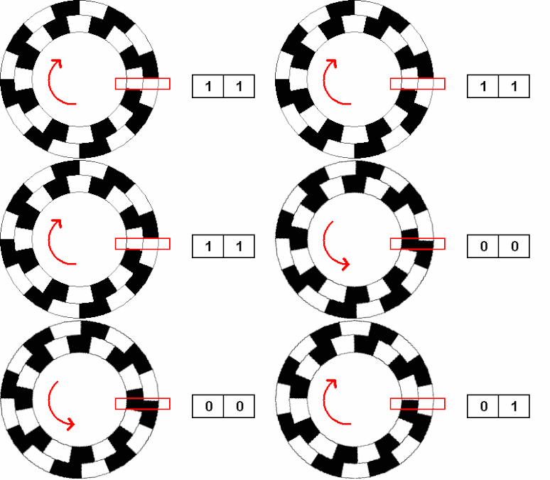
The Rotary Encoder is a device that generates two square wave output signals and a common pin used to determine the rotating position and direction. It works by having a disk with evenly spaced contact zones connected to the common pin and two separate contact pins, A and B.
.png) |
| Rotary Encoder Mechanism |
Pins A and B connect with the common pin as the disk rotates, generating the two square wave output signals. The rotated position can be determined by counting the number of pulses in the signal. However, both signals must be considered simultaneously to determine the rotation direction.
The two output signals are displaced at 90 degrees from each other and are out of phase. If the encoder rotates clockwise, output A is ahead of output B. If the encoder rotates counterclockwise, the output signals have equal values. The rotation direction can be determined by observing the values of the two signals at the time of change, from High to Low or Low to High.
 |
| Rotary Encoder Sensor Mechanism |
Parts Required
To interface a rotary encoder with an ESP32, you will need the following components:
- ESP32 microcontroller
- Rotary encoder
- Breadboard and jumper wires
Connecting the Components
To connect the components, you will need to follow these steps:
- Connect the power and ground pins of the ESP32 to the power and ground rails of the breadboard. Follow the circuit diagram.
- Connect the two output pins of the rotary encoder to two digital input pins on the ESP32.
- Connect a 10k ohm pull-up resistor between the rotary encoder's output pins and the power rail.
Circuit diagram of ESP32 Rotary Encoder
Programming the ESP32
Once the components are connected, you can begin programming the ESP32 to read the rotary encoder's inputs and perform an action based on the rotation of the shaft. To do this, you will need to use the Arduino Integrated Development Environment (IDE) and write a sketch that implements the following steps:
- Initialize the digital input pins of the ESP32 that are connected to the rotary encoder.
- Read the state of the rotary encoder's output pins.
- Determine the direction of rotation based on the state of the output pins.
- Perform an action based on the direction of rotation, such as adjusting an LED's brightness or controlling a motor's speed.
Arduino code for Encoder with ESP32
ESP32 Code breakdown
Pin Definitions:
#define ENCODER_B 14
#define BUTTON 12 code-box
The digital pins connected to the rotary encoder's two output signals and the push button are defined as constants with names ENCODER_A, ENCODER_B, and BUTTON. These constants make the code more readable and easier to modify.
Variables for Encoder and Button:
int lastEncoderPos = 0;
int buttonState = 0;
int lastButtonState = 0; code-box
In these lines, the variables encoderPos and lastEncoderPos are used to keep track of the current and previous positions of the rotary encoder, respectively. The variables buttonState and lastButtonState are used to keep track of the current and previous state of the push button, respectively.
Setting pin modes:
pinMode(ENCODER_A, INPUT_PULLUP);
pinMode(ENCODER_B, INPUT_PULLUP);
pinMode(BUTTON, INPUT_PULLUP);
} code-box
In the setup() function, the input mode of the digital pins is connected to the rotary encoder, and the push button is set to INPUT_PULLUP. This means that the internal pull-up resistors are enabled, which is necessary to avoid false readings when the rotary encoder switches between the two output signals or the button is pressed.
Encoder and Button Readings:
encoderPos += (digitalRead(ENCODER_A) == digitalRead(ENCODER_B)) ? -1 : 1;
buttonState = digitalRead(BUTTON);
if (buttonState != lastButtonState) {
if (buttonState == LOW) {
encoderPos = 0;
}
lastButtonState = buttonState;
}
if (encoderPos != lastEncoderPos) {
lastEncoderPos = encoderPos;
Serial.println(encoderPos, DEC);
}
} code-box
In the loop() function, the current position of the rotary encoder is calculated by checking the state of the two output signals using the digitalRead() function. If the two signals are the same, the encoderPos are decreased; if they are different, the encoderPos are incremented.
The current state of the push button is also read using the digitalRead() function and stored in the buttonState variable. If the button state has changed since the last reading, the encoderPos is reset to zero if the button is pressed (i.e., buttonState is LOW). The lastButtonState variable is then updated to reflect the current button state.
Finally, if the position of the rotary encoder has changed since the last reading, the encoderPos is printed to the serial monitor using the Serial.println() function.
Benefits of Using a Rotary Encoder
There are several benefits to using a rotary encoder with an ESP32, including:
- Precise Control: Rotary encoders control a shaft's rotation, making them ideal for volume control, motor control, and user interfaces.
- Robust Design: Rotary encoders are durable and can withstand repeated use, making them a reliable choice for demanding applications.
- Easy to Use: Rotary encoders are simple to connect and program, making them popular for hobbyists and beginners.
Conclusion
Interfacing a rotary encoder with an ESP32 is a straightforward process that can provide precise control and reliability in various applications. By following the steps outlined in this article, you can easily add a rotary encoder to your next ESP32 project.

